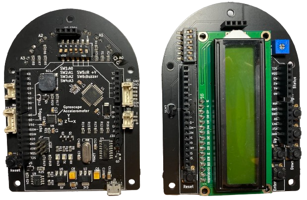

This is an enhanced version of Arduino UNO. In additional to the ATmega328P microcontroller, below are additional features built into the board.
Gyroscope and accelerometer sensor is connected to I2C at address 0x68.
Speaker is connected to digital pin 8 which can be enable or disable by SW6
Infrared transmitters and receivers. Four transmitters can be enabled or disabled by SW5. Four receivers are connected to analog pins A0, A1, A2, and A3, and can be enabled or disabled by SW1 to SW4 respectively.
A LM555 IC and circuit to enable power bank power supply.
Connectors connecting I2C and digital pins 2 to 7 for communicating with external boards and for robotic control.
Header pin for connecting to ultra-sonic module. Trigger is connected to pin D9, and echo is connected to pin D10.
Three LEDs are connects to digital pins D0(UART receive pin), D1(UART transmit pin), and D13(SPI SCK pin).
Power section supplies voltages to the components in the board and external devices through header pins. VIN is input voltage from external power supply between 6 and 12 Volts, this voltage is stepped down to 5 Volts and 3.3Volts for providing power to ATmega328P and MPU6050 respectively. External boards or circuits can source power from these voltages through the header socket.
The board can be powered through the micro-USB port, either connecting to a computer or a power bank.
The microcontroller board consists of the following:
ATmega328P microcontroller (U1)
Gyroscope and accelerometer (U6)
Speaker (BZ1)
USB IC (U4)
LM555 IC (U8)
Infrared transmitters and re- ceivers (D1 to D8)
Reset button
There are six analog pins namely A0 to A5, A0 to A3 are connected to built-in infrared sensors, and can be activated through SW1 to SW4. I2C SDA and SCL are shared with A4 and A5.
Digital pins are D0 as well as serial Receive, D1 as well as serial Transmit, D2 is Interrupt INT0, D3 is Interrupt INT1 as well as PWM, D4, D5 sup- ports PWM, D6 supports PWM, D7, D8 connects to a buzzer and can be activated through SW6 switch, D9 supports PWM and connected to ultra- sonic sensor Trigger pin, D10 supports PWM and connected to ultrasonic sensor Echo pin, D11 is MOSI, D12 is MISO, and D13 is SCK which is connected to a red LED labeled D13 on the board.
The buzzer can produce sound by varying HIGH and LOW signals output from D8 or using Arduino tone() function. SW6 need to be switched on to enable the buzzer.
MPU6050 is a 6-axis motion tracking device that consists of a 3-axis gyro- scope and a 3-axis accelerometer. Interface to this device is through I2C at address 0x68.