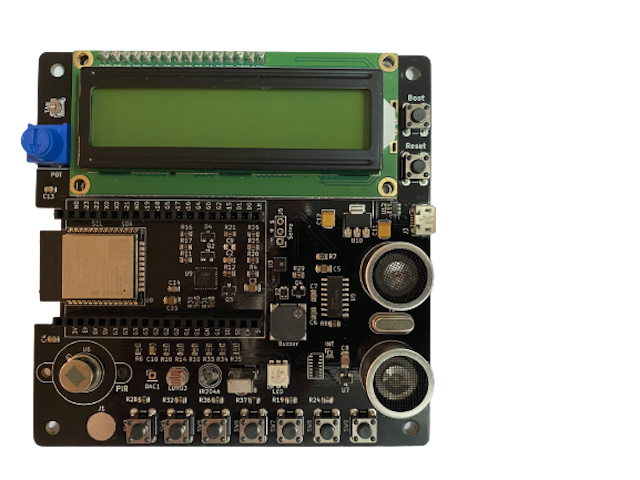
ESP32 microcontroller is a System on Chip (SoC) microcontroller with built in WiFi and Bluetooth, which means we can write programs for communicating between microcontrollers or between microcontroller and computer through WiFi or Bluetooth. The ESP32 sensor board has built in sensors connected to a ESP32 microcontroller, this reduces the risks of damaging the sensors and microcontroller if incorrectly connected, reduces the possibility of connecting sensors to different pins as in programs, and reduces time taken to connect sensors to the microcontroller.

Below are descriptions of sensors, and connections to the microcontroller.
Buzzer is a device that produces sound at different frequencies, so we can produce musical notes by sending different frequencies to the buzzer. A buzzer is connected to Input/Output pin 5 or IO5 on the microcontroller.
A tri-colour LED is on the sensor board. This single LED contains three LEDs, Red, Blue, and Green, and are connected to IO12, IO13, and IO14 respectively.
A pair of ultrasonic sensors, one transmitter that transmit radio frequency and one receiver that receive radio frequency. Transmitter sensor is connected to IO17, and receiver sensor is connected to IO16 on the microcontroller. This pair of sensors can be used for detecting objects, and computing distance of objects placed in front of the sensor.
A SD card reader is built on the sensor board, data are read and write to the SD card using Serial Peripheral Interface (SPI). SPI pins that control the SD card are select/control pin connects to IO15, SCK connects to IO18, MISO connects to IO19, and MOSI connects to IO23.
IO25 is reserved for digital to analog conversion. It is an 8-bit Digital to Analog Converter (DAC) for converting between 0 volt and 3.3 volts to a range of numbers between 0 and 255. This pin can be used for digital input and output, and Analog to Digital Converter (ADC) as well.
Infrared receiver is for receiving infrared rays send from remote controllers, such as TV, air-conditional, fan remote controls. This is an infrared decoder, where encoded signals received are send to IO26.
Infrared transmitter is for sending infrared rays either directly to an infrared receiver or be encoded before transmitting. It is connected to IO27.
Touch sensor is connected to IO32. The surface of this pad measures capacitance variation when touched.
IO33 is assigned for analog input. Seven switches are connected to this pin as voltage dividers for setting different voltage levels. These switches can be used individually or in combination to set different voltage levels.
A Light Dependent Resistor (LDR) is connected to IO34. This sensor is for measuring light intensity, where its resistance changes according to light intensity. High light intensity causes the resistance to go low.
A potentiometer or POT is connected to IO36. This POT produces analog voltage between 0 volt and 3.3 volts to IO36. The voltage can be mapped to 9, 10, 11, or 12 bits numbers. For instance, a 12 bits number \(2^{12}\) ranges between 0 and 4095.
A Passive Infrared Sensor is connected to IO39. This sensor has a sensing range of ten feet radius, and is activated when an object moves within this range. A HIGH signal is set on pin IO39 when activated, and LOW otherwise.
AHT21 temperature and humidity sensor is built on board. This sensor is accessed through \(\text{I}^2\text{C}\) at address 0x38. \(\text{I}^2\text{C}\) uses two pins serial clock SCL connects to IO22 and serial data SDA connects to IO21.
A 16x2 Liquid Crystal Display(LCD) is built in and can be accessed through \(\text{I}^2\text{C}\) at address 0x27. The address can be changed by shorting jumpers A0, A1, and A2 at the bottom of the board. Connecting A0 change the address to 0x26, connecting A1 change the address to 0x25. The complete list is shown in Table 1.1.
| Address | A2 | A1 | A0 |
|---|---|---|---|
| 0x27 | Open | Open | Open |
| 0x26 | Open | Open | Connected |
| 0x25 | Open | Connected | Open |
| 0x24 | Open | Connected | Connected |
| 0x23 | Connected | Open | Open |
| 0x22 | Connected | Open | Connected |
| 0x21 | Connected | Connected | Open |
| 0x20 | Connected | Connected | Connected |
Since there are eight addresses to choose from, so up to eight LCDs can be connected to the board where each LCD is assigned with a unique address.