Make your own Arduino board
This is an Arduino Duemilanove compatible board for people who would like to make their own Arduino board, learn to solder, know more about Arduino board, and experiment with the circuit.
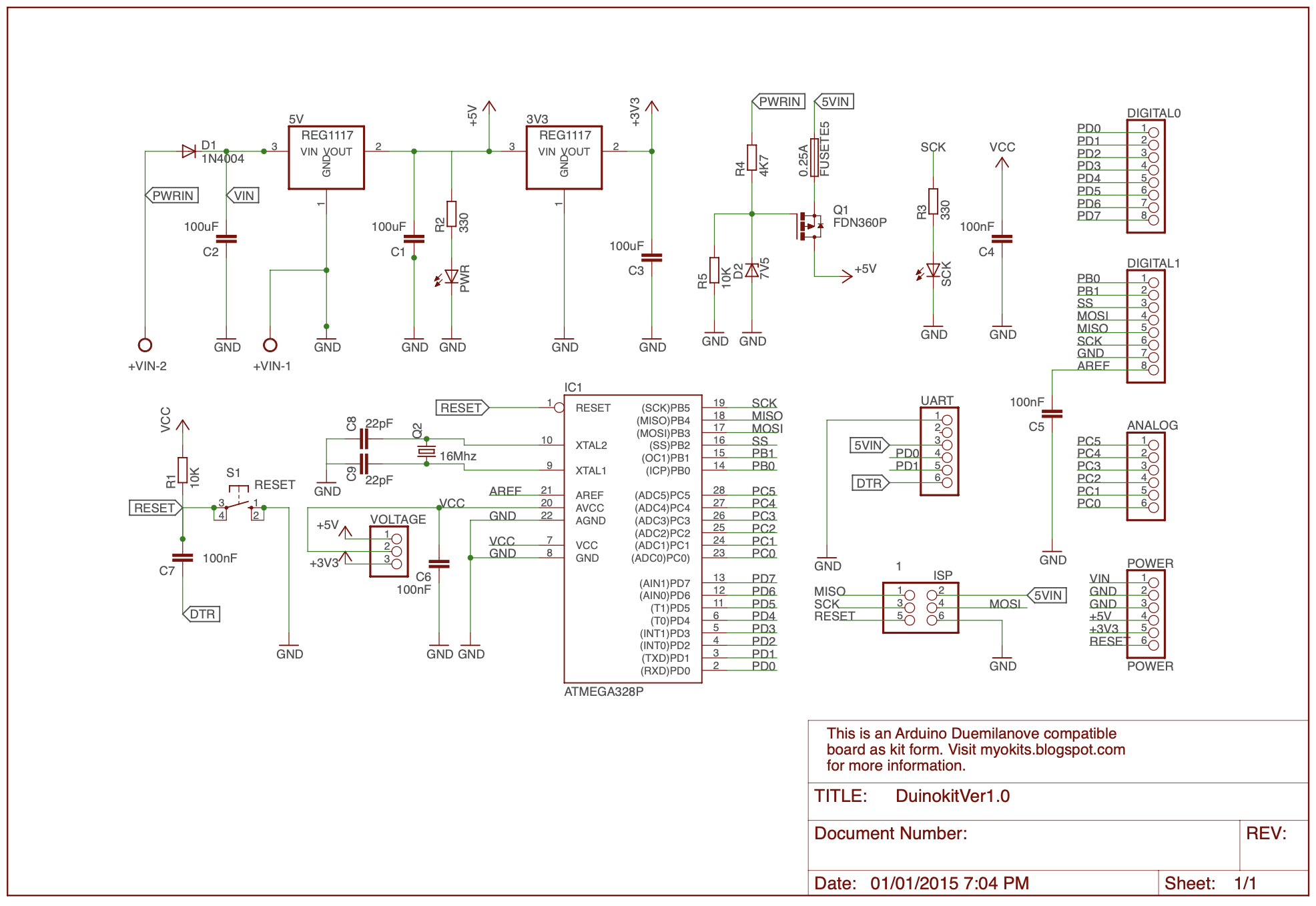
Below are several differences between Arduino Duemilanove/UNO and this DIY board.
Added a switch to switch between 5V and 3.3V
Replaced the external power input jack to screw type
Replaced the opamp that controls the P-Channel MOSFET with a resistor and zener diode circuit
Removed the FTDI chip
Made the external power supply as default power
Reduced the fuse to 250mA
The addition of the switch is to make this board easier to work with external circuits that accept 3.3V and this eliminates voltage conversion between 5V and 3.3V.
Using the screw type power connector is easier to connect to external power supply. Fixed voltage power adapters may not provide the right polarity to the board, that is +ive inside and ground outside connection.
Without the opamp simplifies the circuit, but comes with a cost of drawing additional few milliampere current. The current drawn can be reduced by replacing R4 or removal of R4 and the zener diode entirely.
The FTDI chip is removed due to this chip is surface mount, so it is rather challenging for people who do not have the right equipment to solder the chip.
Making the external power supply as the default for providing higher current to support external shields, and adding a 3.3V regulator to support up to 500mA current for 3.3V instead of 50mA tapping from FTDI chip in Arduino Duemilanove.
The fuse is reduced to 250mA to safeguard USB devices that could not provide high current load.
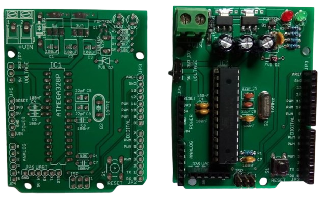
Below is a screen shot of the blank PCB and an assembled board.
Building the board
Top part of the circuit board, as shown in the photo below, is the power section. You may solder the 1N4007 rectifier D1(pay attention to the cathode marking on the diode. The marking on the diode should face the same direction as the diode printed on the board.), 5V and 3.3V regulators, and the P-channel MOSFET, as shown in Figure 3. There are markings printed on the bottom left of the regulators, 5.0 and 3.3 stand for 5V and 3.3V respectively. The 5V regulator should go to the left next to 1N4007. These components are soldered first, because the electrolytic capacitors may get into your way if they are soldered.
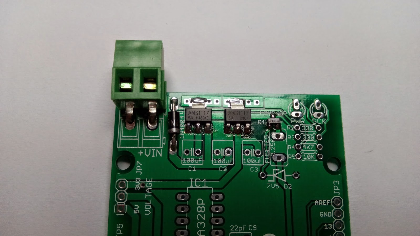
The power connector is designed to plug onto the PCB; however, it is rather high that it may be an obstacle to some shields. To avoid this, you may want to bend the two pins on the connector and plug it into the PCB as shown in the photo. Be careful when you bend the pins, as they may break. There are some shorter power plugs, but are not as robust as this green plug.
Once the above is done, then solder the three electrolytic capacitors, the red power LED, and the 1K ohm resistor R2. Note that 330 ohm is printed on resistors R2 and R3 which is too low value for the LEDs. The 25V 100uF electrolytic capacitor should go to C1 and the other two 16V 100uF capacitors go to C2 and C3. The negative(the shorter pin or the pin that has a white line on the capacitor) should be connected to the ground or the left of the two holes for the capacitors. The shorter legs on the LEDs are the cathodes and should go to the ground or the holes next to PWR and SCK. You can identify the cathode of an LED using an analog meter, when the positive and negative probes are connected to an LED and it lights up, then the positive probe is connected to the cathode.
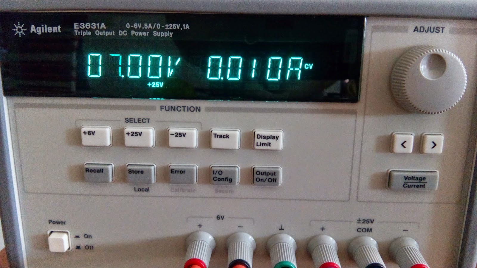
You may test the circuit now by supplying a voltage between 7V and 9V to the board. There is a marking +VIN on the PCB, and positive should be connected to this pin of the power connector. Note that the higher the voltage is supplied to the board, the 5V regulator would become hotter. Try not to supply more than 12V to the board, this may damage the regulator. This applies to Arduino Duemilanove/UNO/Mega boards that use similar 5V power regulators. In this example, a 7V is applied to the board and it draws 10mA as indicated in the power supply.
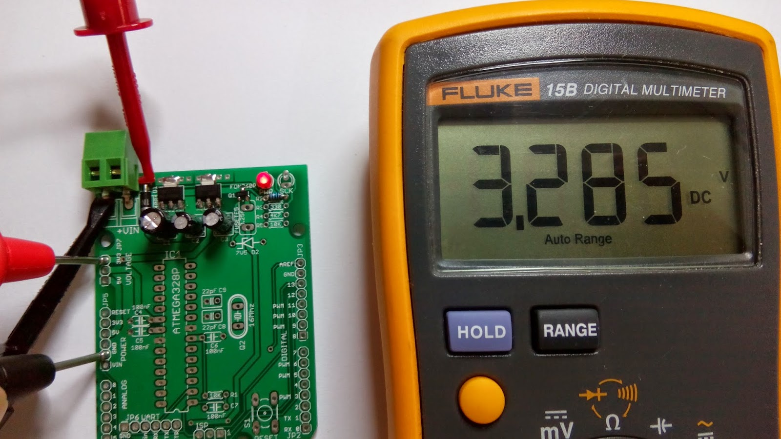
Once you have supplied power to the board, the red LED should light up. Test the output voltages by placing the negative probe of a multimeter on any of the pins that marked GND, and the positive probe goes to 5V and 3.3V to test their respective voltages. Figure 5 shows the output of the 3.3V regulator, that is 3.285V.
The next step is solder the 250mA fuse, zener diode D2, 1K ohm resistor R3, 4.7K ohm resistor R4, 10K ohm resistor R5, and the green LED marked SCK. This green LED is connected to pin D13, and it should blink when the circuit is built and powered up because the microcontroller is preloaded with Dumilanove bootloader and it blinks pin D13.
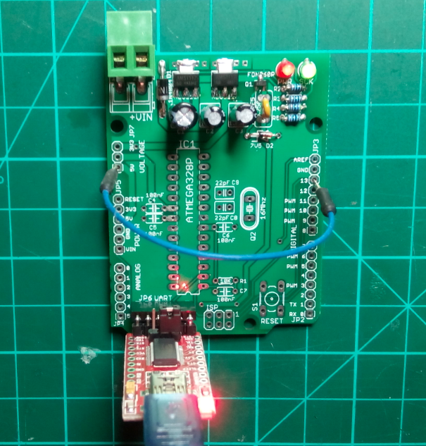
You may check the P-channel MOSFET circuit by connecting a USB module to the board, and the red LED should light up. Connect pin D13 to 3.3V or 5V, and the green LED should light up. These are shown in Figure 6. Make sure that the USB module is inserted onto the board correctly, where the GND or ground for both the USB module and Duinokit board should match. Figure 7 shows some of the USB modules that can be used with Duinokit. Any USB module that uses FTDI's chip, and the pins are in the same sequence as the board should work. That is in the sequence shown below.
GND, CTS, VCC, TX, RX, DTR.

You may proceed to solder all other components. Insert the Atmel328 microcontroller, make sure the little gap or pin 1 is facing the ISP connector. Once you power up the board, you should see the red LED lights up, and the green LED blinks at 1 second interval.
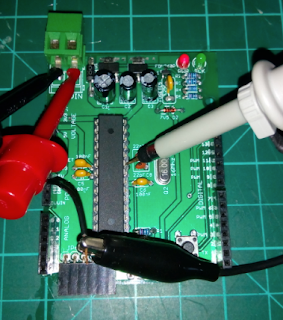
If you happened to have an oscilloscope, you may test the clock by probing on the pins connected to the crystal, they are pin 9 and 10 on ATMEGA328P (not the Arduino board digital pin header). Photo below shows a sample of the waveform, which shows that the clock is running at 16Mhz.
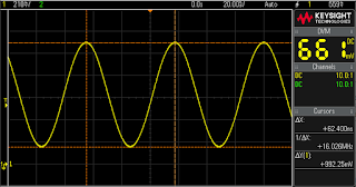
Photo below shows where to place the probe on ATmega328 pin.
